 |
|||
|
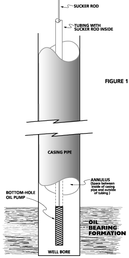
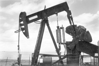
Oil wells that use pumping units to artificially lift oil from the well are also wells that generally produce natural gas in addition to oil.When the ground oil-formation releases oil into the well bore, the formation also releases natural gas into the casing annulus. The annulus is the volumetric space between the inside diameter of the casing and the outside diameter of the tubing that is located within the casing. The tubing is the string of pipe through which the sucker-rod string operates the down-hole oil pump attached to the bottom of the tubing-string (see Fig. 1). The down-hole pump forces the oil up through the tubing to the well-head, and then into the flow line away from the well-head.The oil formation pressure moves oil from the formation into the well-bore, specifically into the casing annulus at the location of the down-hole pump. As oil is released from the formation into the well bore, gas
is also released from the oil formation. This released gas will
fill the annulus all the way up to the surface casing-head. When
the casing-head gas pressure becomes equal to or exceeds the flow
line pressure, the gas leaves the casing-head and enters the same
flow line as does the well-head oil. |
|||
| The accumulated gas in the casing annulus exerts a back-pressure on the down-hole oil formation. This down-hole back pressure (hydrostatic pressure) acts on the oil formation in a manner to prevent or restrict free flow of oil and gas from the formation.When the hydrostatic pressure created by the casing gas is reduced, flow of oil and gas from the formation increases, and thus production of oil and gas increases. | |||
| For more than one hundred years, various means of “well head compression” have been used to reduce the hydrostatic pressure by removing the casing gas. Well Head Compression refers to the removal of casing-head gas, and the compression of that gas into the higher pressure flow line. Many types of conventional compressors have been used over the years in attempts to successfully and reliably reduce hydrostatic pressure through removal of casing-head gas. Most of the past attempts were forced-lubrication units that required considerable maintenance, adjustments, and attention. And they were prone to continual failures for lack of adequate and practical technology. | |||||
 |
|||||
|
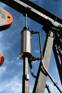
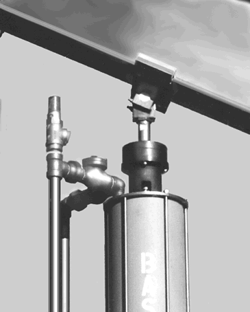
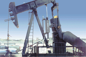
The Basil Beam Compressor (BBC) was developed in the period since 1992 using state-of-the-art materials, seals, and engineering technology. The result is the world’s unique walking beam gas compressor. It’s powered by the force of the walking beam of a typical pumping unit. Power requirement for the BBC is approximately 3 to 7 horsepower. Both maintenance free and adjustment free, replacement of seals is typically required, at minor cost, about every eight (8) months of continuous operation. An oil-production chart for a well generally follows a curve like this. |
|||||
 |
|||||
|
When a BBC is installed at a well, an initial “flush” production of oil and gas occurs. This flush increase is due to the fact that when the BBC begins operation, the casing annulus is full of gas at whatever pressure is at the flow line and the BBC removes the gas at a rapid rate of discharge. As the gas removal occurs, oil is released from the down-hole formation by the sudden and significant drop in hydrostatic pressure. A typical oil discharge chart looks like this. |
|||||
 |
|||||
| After the flush-production period, the oil flow settles out at a different production level. The extent of the new production level is primarily a function of the permeability and porosity of the oil formation and, of course, of the efficiency of the walking beam gas compressor. The BBC units are the most reliable and efficient beam compressors that have been developed and offered to the oil industry. | |||||
